Table of Contents
Introduction
Nesting is the process of arranging parts on a sheet in such a way that they occupy a minimum of space. The main objective of nesting is usually to minimize waste when cutting sheet material.
QCAD/CAM comes with an integrated nesting tool that allows you to fully automatically arrange parts onto a single or multiple sheets.
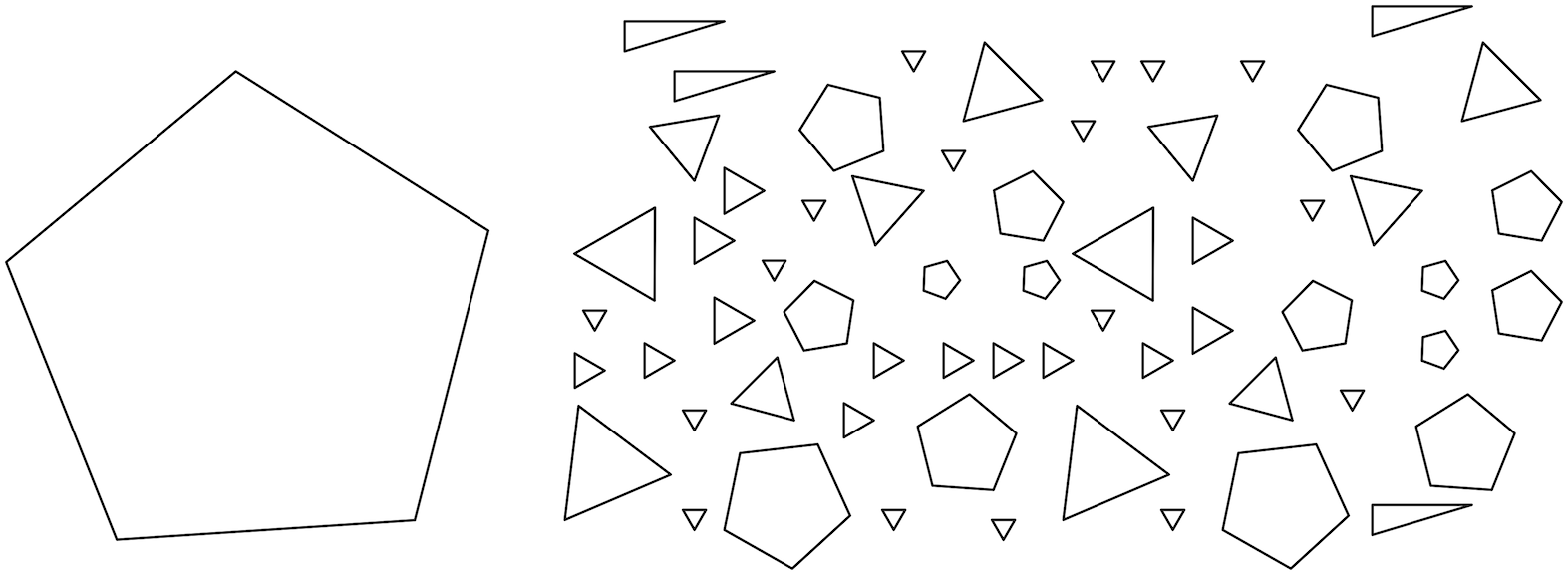
In the example below, the sheet is shown in black at the left and the parts in various colors. A possible solution as proposed by QCAD/CAM is shown at the right.

Features
- Placing smaller parts inside holes of larger parts (part-in-part placement)
- Nesting based on the actual shape of a part (true shape nesting)
- Automatic rotation of part at configurable angles
- Automatic alignment of parts to X/Y axes
- Nesting polylines, loose entities, splines, ellipses and texts
- Mark parts to be nested multiple times
- Multithreading
Preparation of Parts
A "part" is a closed shape, optionally with holes. Larger holes in a part may be used for the placement of other, smaller parts as shown above for the hole in the large rectangular orange part.
A part does not necessarily have to be surrounded by a polyline but can also consist of loose, connected entities (lines, arcs, ellipse arcs, splines, circles). A text entity may also be used as a part. If a part contains a text entity, that text entity stays with the part and is not regarded as a hole. This is the case for the red part above. Texts may be used to label or track parts.
To nest the same part multiple times, select the part and choose CAM > Set Nesting Quantity. A dialog allows you to enter the desired quantity for that part.
Preparation of Sheets
A "sheet" is also expected to be a closed shape, optionally with islands (holes). Sheets can consist of polylines, lines, arcs, ellipse arcs or splines. If a sheet contains an island, that island will not be used to place parts during nesting.
Nesting
Select the parts to nest using the QCAD/CAM selection tools.
Start the nesting tool and choose the sheets to nest into by clicking any entity of each closed sheet to use.
For detailed instructions and an explanation of the various nesting parameters, please refer to the reference manual.
Set rotations to "1" to insert all parts without rotating them. A value of 4 usually yields good results for parts with many right angles and parallel edges.
Right-click when you're done choosing sheets.
QCAD/CAM starts to produce possible solutions to arrange as many parts as possible in the chosen sheets.
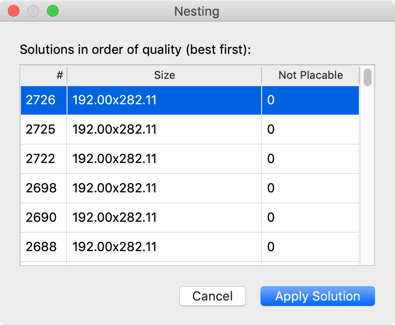
As soon as solutions become available, they are listed in the table of the nesting dialog:

The nesting algorithm continuously looks for new, better solutions and lists them in descending order (the best solutions are listed at the top, the worst at the bottom). If a solution is only a partial solution (meaning some parts could not be placed in the chosen sheets), the number of parts that were not placed is shown in the last column.
Previewing Solutions
The suggested solutions can be previewed while QCAD/CAM is looking for other solutions by clicking on one of the rows in the table.
Stopping the Nesting Process
If a good solution has been found, click the Stop button to stop looking for better solutions.
Choosing and Applying a Solution
The nesting dialog is now shown again with all the solutions found until the nesting process was stopped. The suggested solutions can now be previewed again until the preferred solution has been identified. To apply the selected solution, click Apply Solution.
Examples
Alignment Left - Bottom:

Alignment: Left - Top:

Alignment: Bottom, nesting inside holes of other parts:

Concave sheet with islands:

Spline shaped island:

Polygons at various angles: