Video Transcript

One of the essential concepts of CAD software is the use of layers. Layers help to organize and manage different aspects of a drawing. In this tutorial, we will explore the basics of layers in QCAD and learn how to use them effectively.
Example drawing: floorplan.dxf
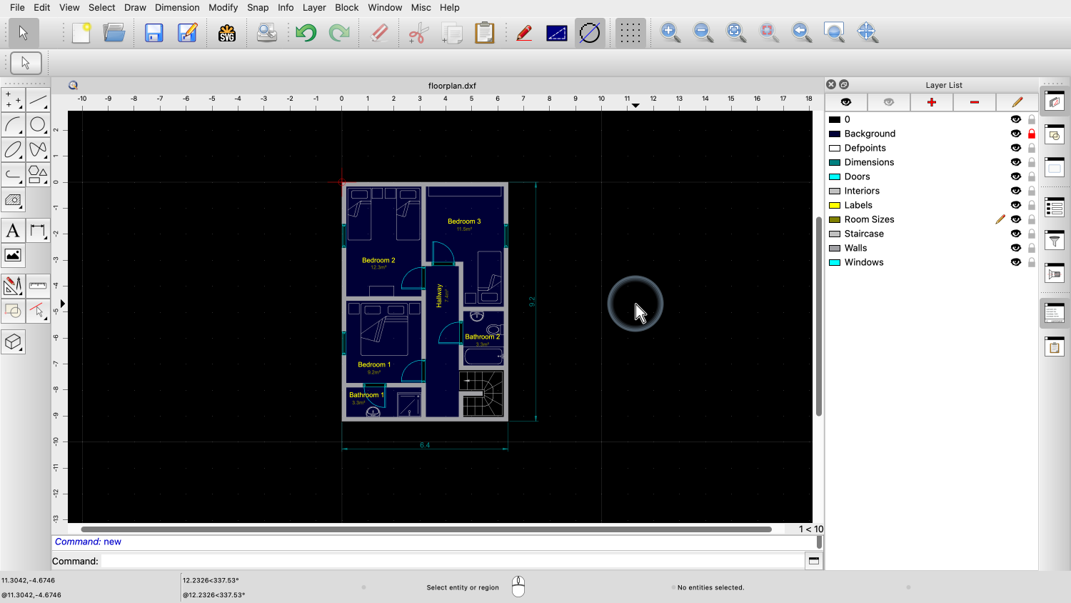
Let's consider this example drawing of a simple floorplan.
This drawing has been organized with a number of layers.

We can see the layers of this drawing in the layer list at the right.
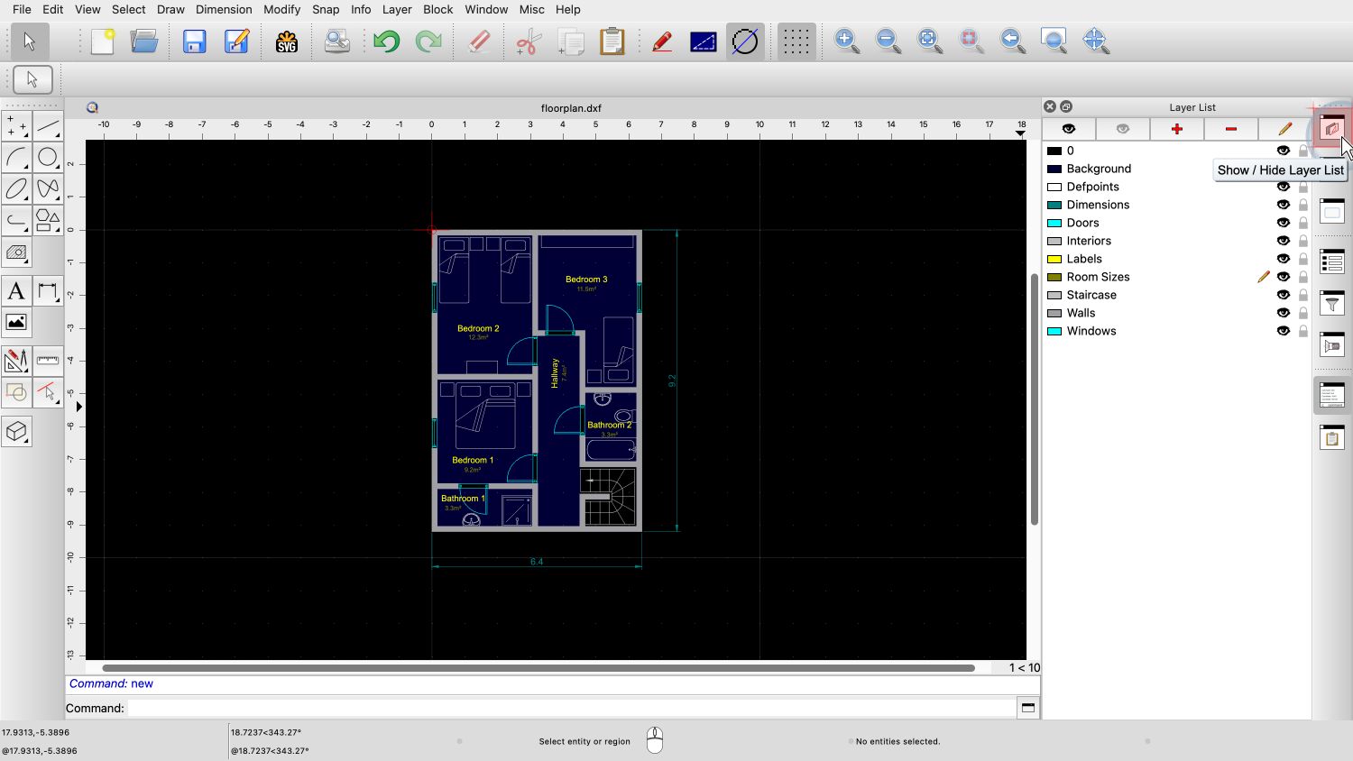
If you cannot see the layer list, you can show it by clicking the button all the way at the top right to toggle the layer list display.
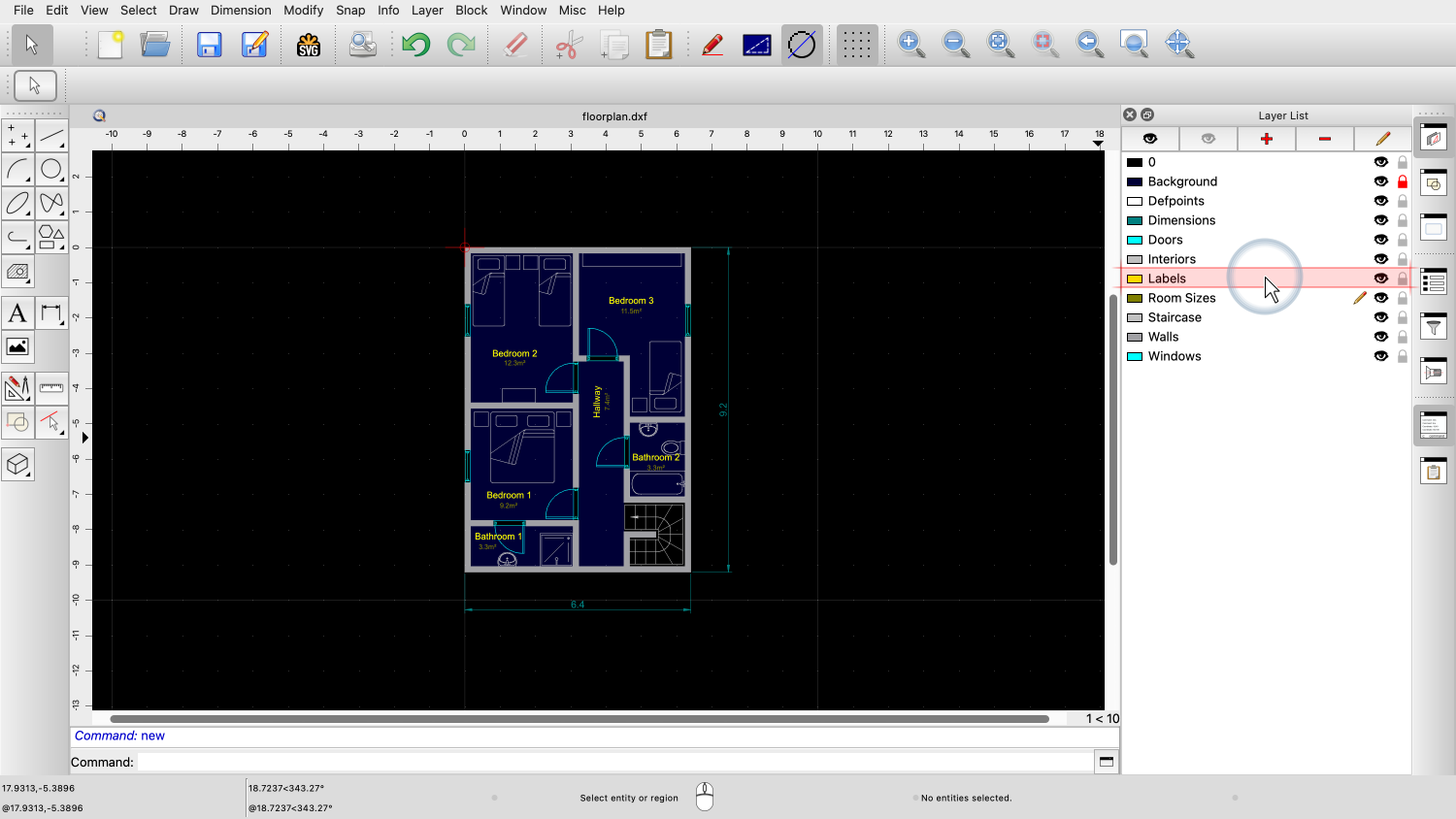
Let's have a look at the layer called "Labels".
The yellow text labels in the drawing indicating the room names are on this layer.

We can see from the color icon in the layer list, that this layer has the color yellow.
Accordingly, all text labels in the drawing are displayed in yellow.

Next to the layer name, the black icon of an eye indicates, that this layer is currently visible.

This means that the entities on this layer are visible.

We can click this icon to switch off this layer.
The layer is now invisible and with it all text labels on that layer.
Note that the text labels have not been deleted from the drawing.
The whole layer is just no longer being displayed until it is switched back on again.
It can be useful to hide certain layers while working on a drawing or for example before printing it.

To switch the layer back on, we simply click the eye icon again.
We can also choose to completely delete a layer from the drawing.

For example, to delete the layer with the room sizes, we first activate the layer by clicking on its name.


Then we click the button to delete the current layer.
Deleting a layer deletes not only the layer but also all the entities on the layer.
To edit a layer, we first activate the layer we want to edit.
Then, we click on the button above the layer list to edit the layer.

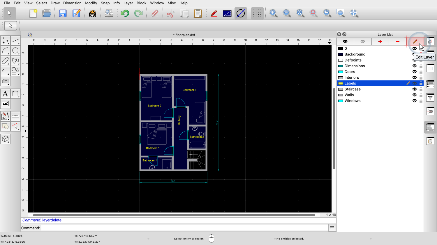
Let's for example change the color of layer "Labels".

In the layer dialog, we can change the name and the attributes of the layer.

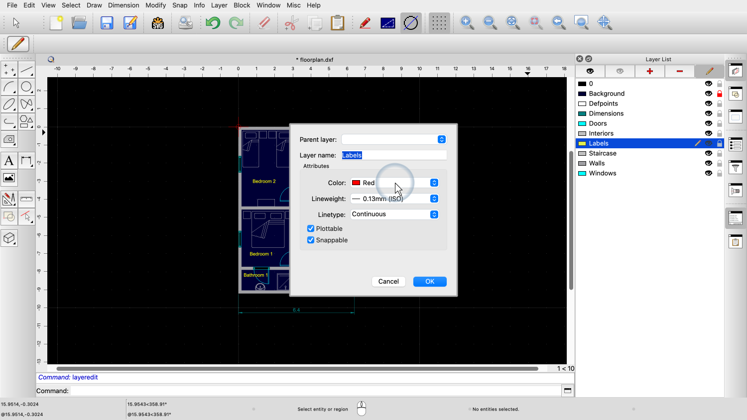
For this example, we change the layer color to red.

The text labels are now displayed in red.
Entities take on the color of the layer they are constructed on and also change their color with the layer color.
This makes it easy to change the appearance of all entities on the same layer at once.
The general idea behind layers is to create a separate layer for each set of entities that have the same or a very similar function in the drawing.
Entities with the same meaning usually also have the same color, linetype and lineweight.
For example, all doors are shown in cyan in this drawing and are placed on a separate layer.
Similarly, a separate layer could be used to add electric wiring, and yet another layer for lights, and so on.

Now, let's start with a new drawing to learn how layers can be created from scratch.
Before we start drawing anything, we create some layers for our drawing.
Note that even this new, empty drawing already contains a layer.

This layer has the name "0".
Layer 0 is the default layer that is always present.
Layer 0 can never be deleted or renamed.
As generally recommended, we leave layer 0 empty and create our own layers for our drawing.
For this simple mechanical drawing, we create three new layers.
The first layer is for all visible edges of our part.
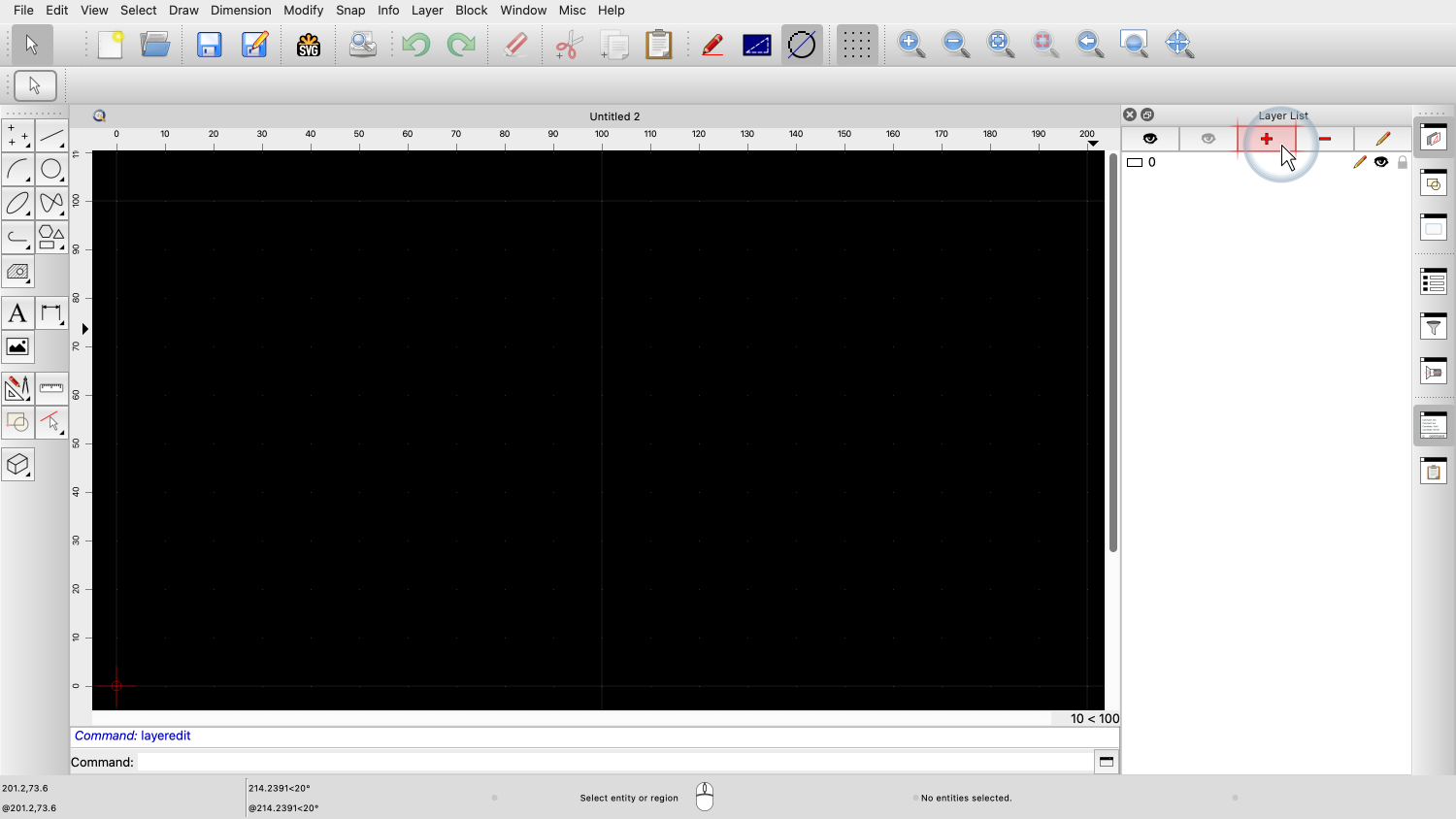
To add this layer, we click the plus button at the top of the layer list.

We set the layer name to "Visible" to indicate that this layer contains all visible edges.
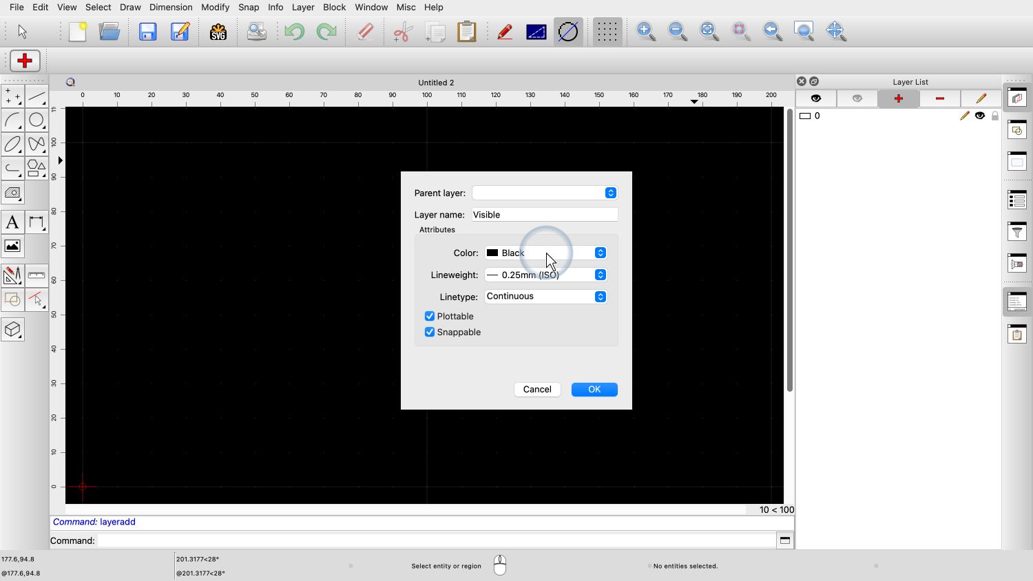
We leave the layer color as black. This color will be displayed as white on the screen and black on a printout.

For the lineweight, we choose 0.5mm.
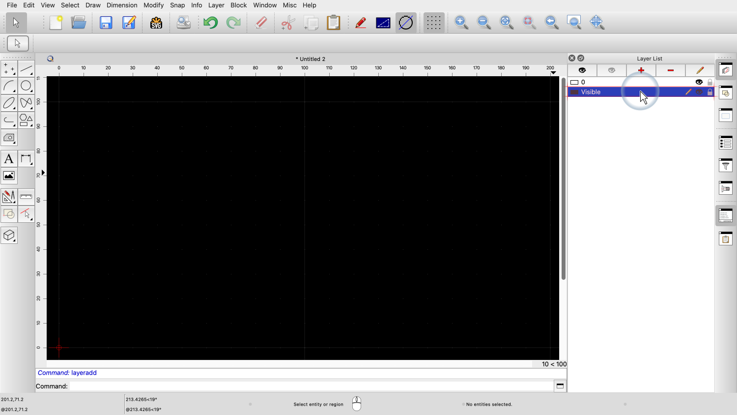
We can now see, that our new layer has been added to the layer list.
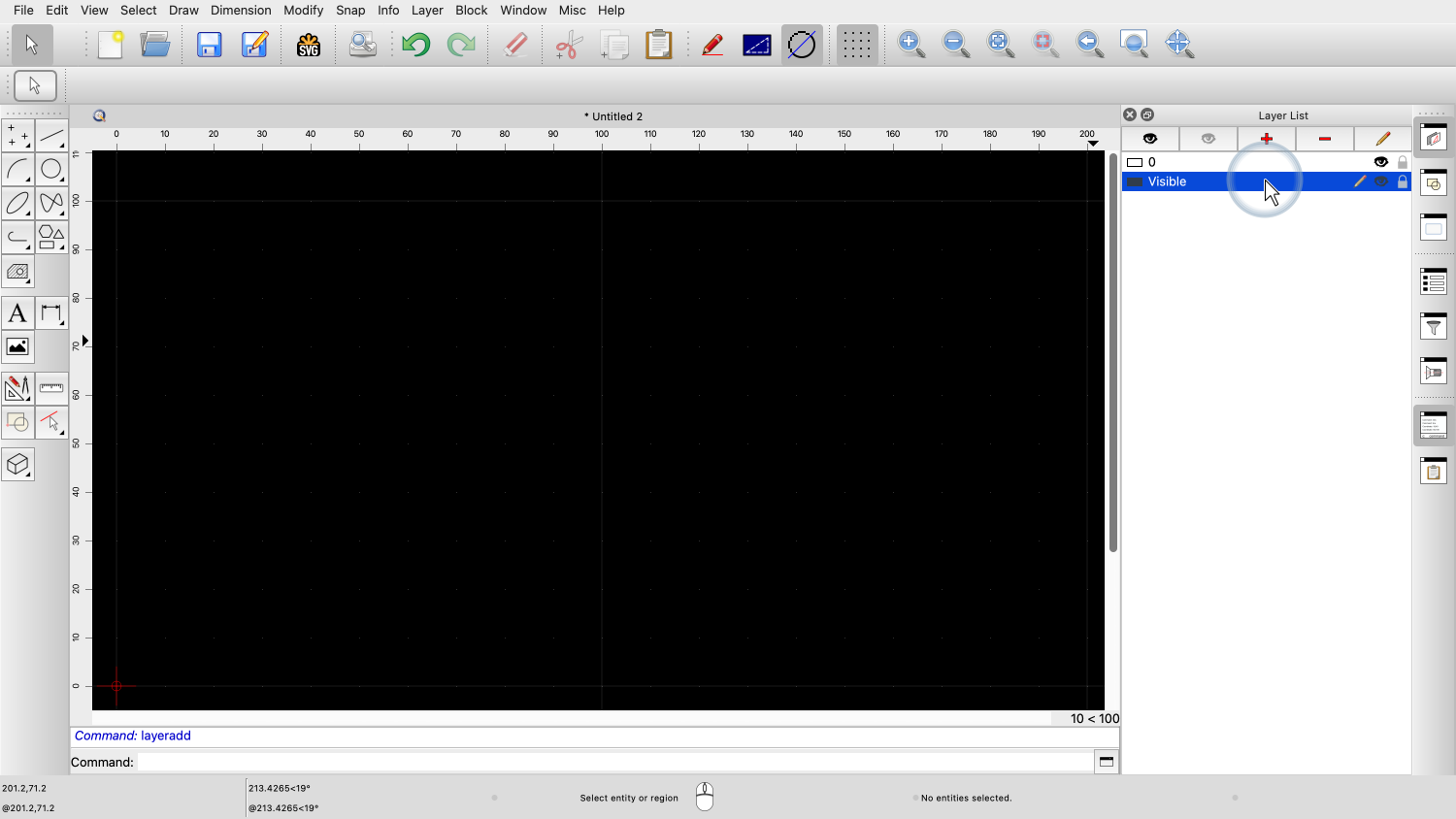
The layer is now ready to be used.

It is also the active layer as we can see from the pen icon next to the layer name at the right.
In the same way, we add a layer for the hidden edges of our part.

We set the layer name to "Hidden".

For the lineweight, we choose 0.25mm.
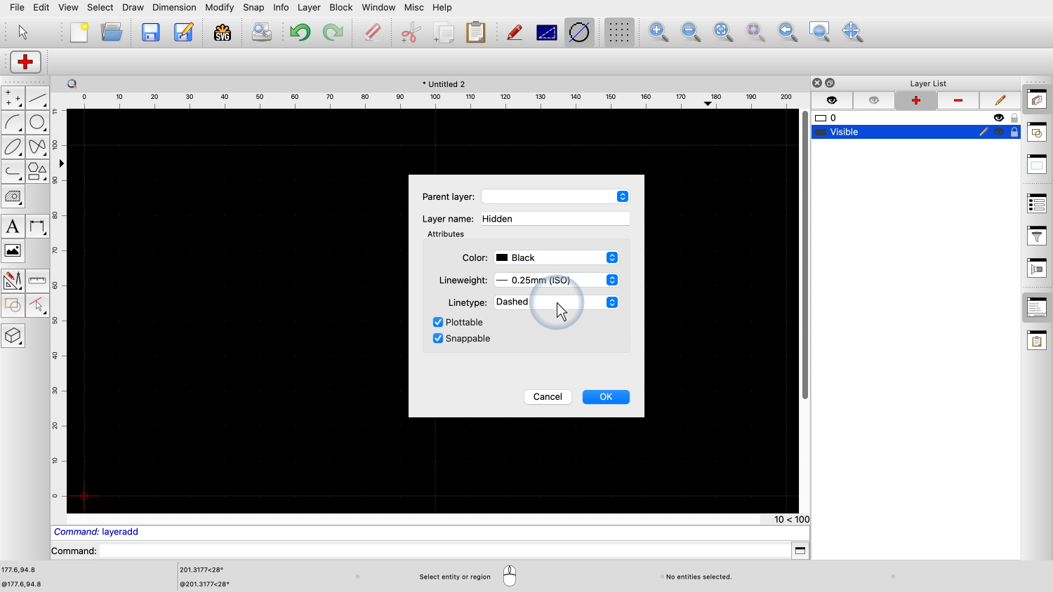
And we set the linetype to Dashed, so the hidden edges can be easily distinguished from the visible edges.
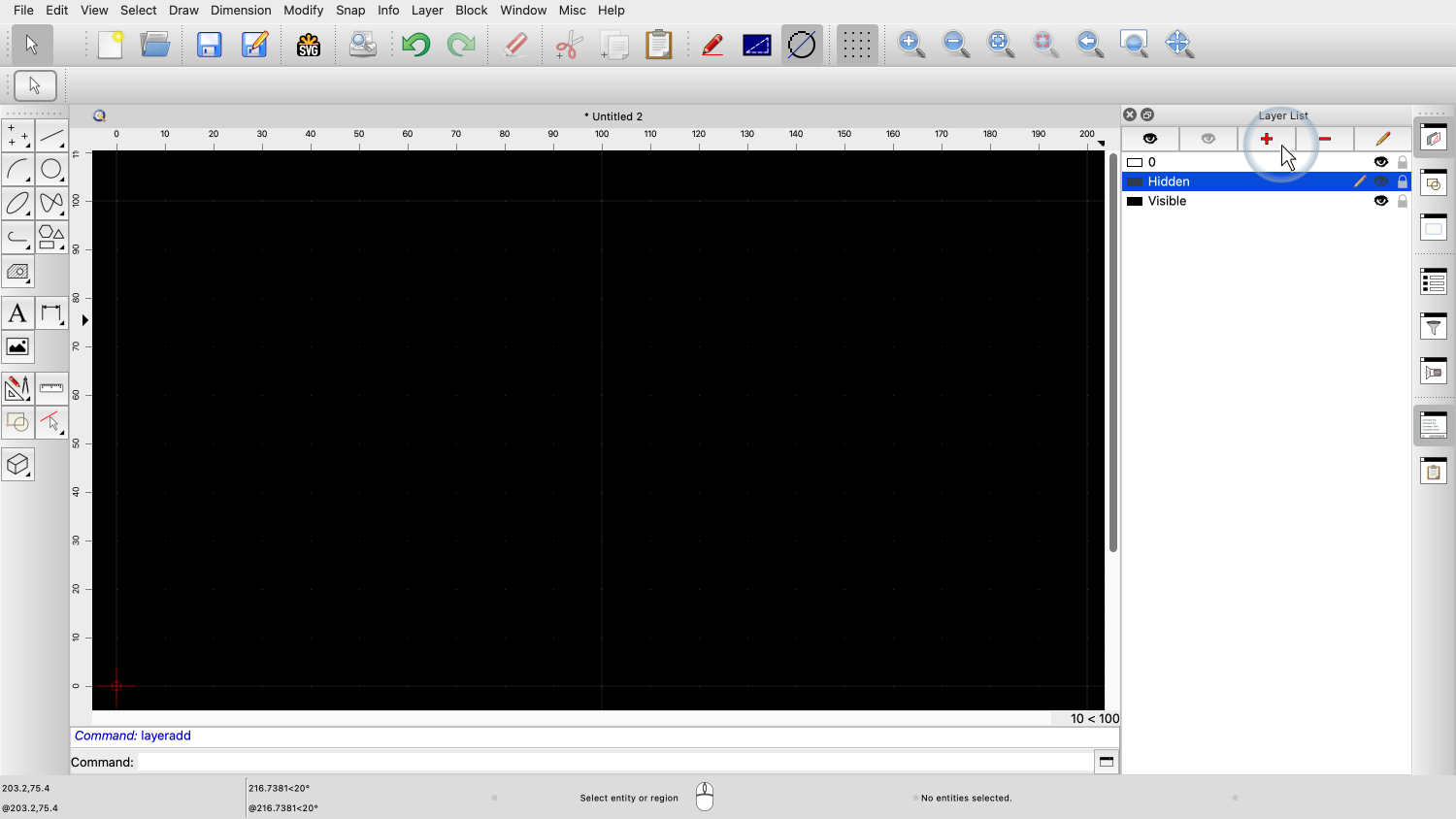
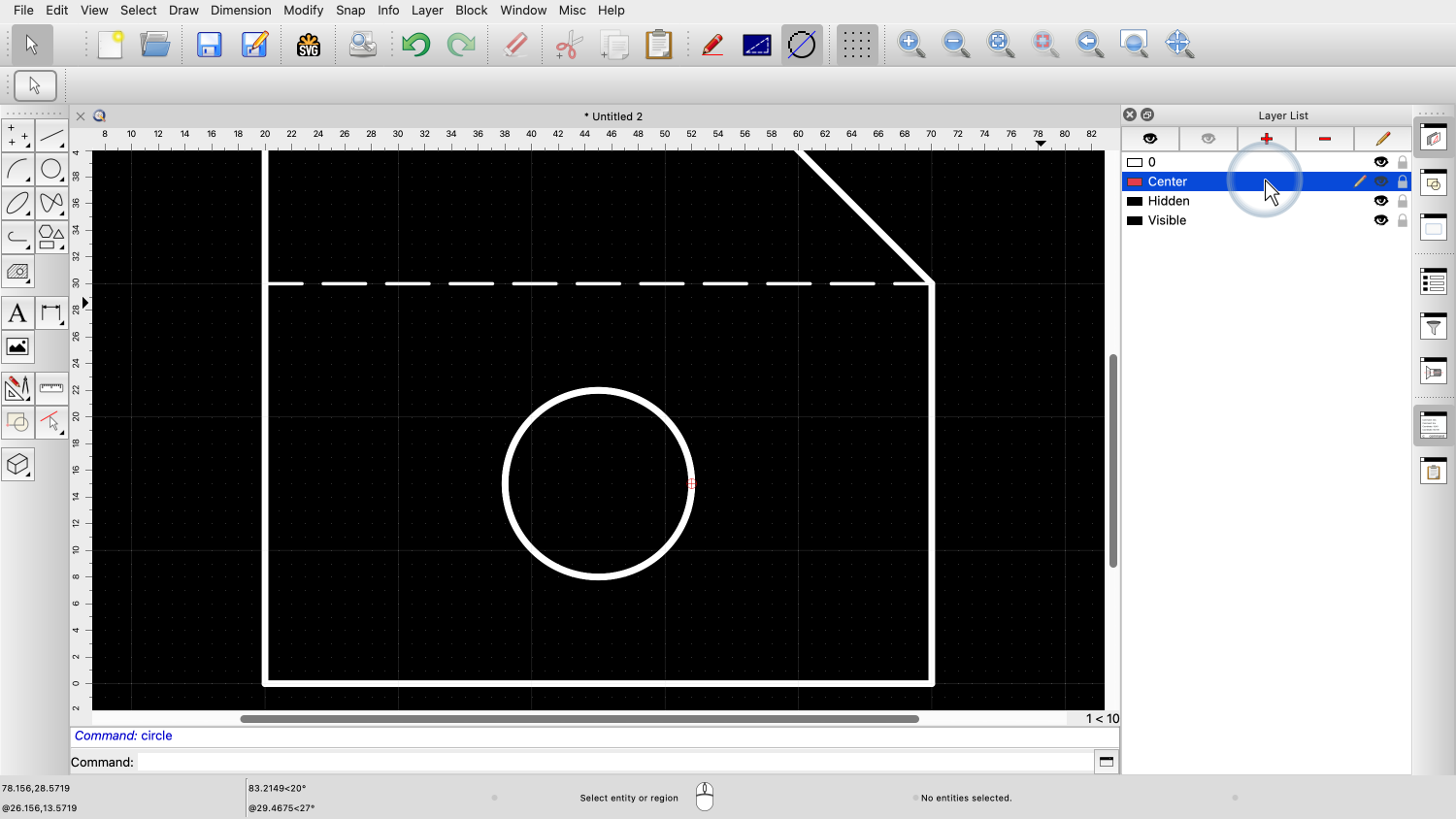
Finally, we add a layer for the center lines of the circles in our drawing.

This layer is called "Center".

We change the layer color to red.

The lineweight of this layer is 0.25mm.

And the linetype is a Dash Dot pattern.

We are now going to create a simple drawing, using these three layers.

First, we activate the layer called "Visible" by clicking on its name.
We draw a simple shape with lines onto that layer.

These are the visible edges of our part.
Next, we activate our layer called "Hidden".

That's the layer with the dashed line pattern.
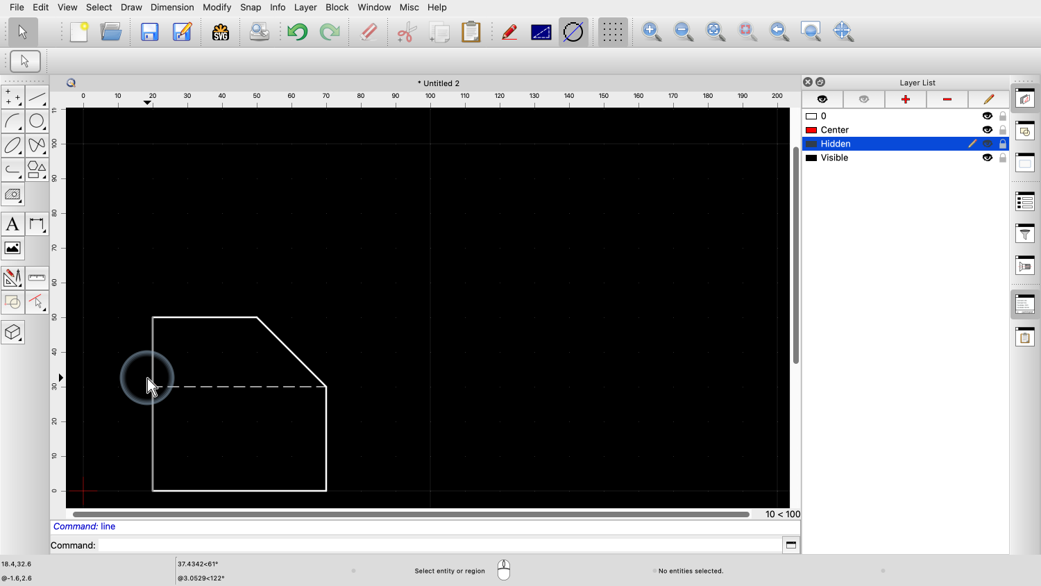
And we draw our invisible edge onto that layer.

As we can see, the lines take on the attributes of the layer they are drawn upon.
The first lines on layer "Visible" are thicker and this last line is thinner and has a dashed pattern.

Let's zoom in a bit to add a circle, representing a drilling in our part.

We add the circle on layer "Visible", since it represents a visible edge of a drilling.
Finally, we draw the center lines for the circle on layer Center.

As expected, these lines are shown in the color and pattern of the Center layer.
Whenever we are drawing something, we need to constantly be aware of what layer is currently active.
We frequently change layers to make sure that every entity is created on the layer it belongs.
If you have previously worked with graphics software, you might think that layers can be used to control the display order to decide what is displayed in the foreground and what in the background.
This is not the case in QCAD (or CAD in general).
Layers in QCAD have no influence on the drawing order of entities.
The layers in the layer list are sorted alphabetically and cannot be ordered differently.
Another common misconception is that layers are used to group entities.
While layers do contain all entities with the same function, they are fundamentally different from groups.
A group or "block", as it is called in CAD, might be used to combine all entities of a mechanical part such as the one we just drew, into a single entity for easier handling.
However, the entities that make up that group can be on various different layers.
Layers are fundamental to CAD, and we will be using them for all of our drawings.
You should now have a basic understanding of layers in QCAD and know how to create, activate and use layers to structure your drawing.
Be sure to practice this with your own QCAD installation.
Thank you for watching this QCAD tutorial.