Video Transcript
In this QCAD tutorial, we will learn the basics about coordinates and how they can be used in a CAD software.

We demonstrate the use of absolute and relative coordinates as well as polar coordinates.
Coordinates are an essential part of each CAD system.
A set of coordinates is like a set of directions that defines exactly where a position in the drawing is located.
Coordinates are made up of two numbers, called [X] and [Y].

[X] refers to the horizontal axis and [Y] to the vertical axis.
Each set of coordinates pinpoints an exact position in the drawing.
The coordinates of a position consist of the distances from the drawing origin in [X] and [Y] direction.
The drawing origin is indicated by the red crosshairs in the drawing window.

The coordinates of the drawing origin are (0,0).

Now, we just moved the mouse pointer to the coordinates (30,50).

The distance from the origin to the mouse pointer in the direction of the [X] axis is 30 drawing units.

And the distance from the origin along the [Y] axis is 50.

We can also see the coordinates of the current position of the mouse pointer in the status bar at the bottom left.

The rulers at the top and left of the drawing area also show coordinates.
We will now use the line tool to demonstrate how we can input coordinates.

We start our line using the grid snap.
Instead of clicking another point in the drawing to define the endpoint of the line, we want to enter the coordinates of the endpoint.

To do this, we click the coordinates button in the tool bar at the left.
We can now enter the coordinates we want to use in the options toolbar at the top.

QCAD immediately previews the coordinates we enter in the drawing area.
This way, we can draw a line to any pair of given coordinates.

We can also choose to use relative coordinates instead of absolute coordinates by ticking the corresponding option.
Relative coordinates relate to the relative zero point instead of the absolute drawing origin.
Right now, the relative zero point is at the start point of the line as indicated by the small red circle.
QCAD automatically moves the relative zero point to the last used position in the drawing.

The coordinates we have entered are now added to the position of the relative zero point.
By entering relative coordinates, we can tell QCAD the desired measurements of our line in [X] and [Y] direction.

To apply the coordinates we have entered, we simply press the enter key or click the green check mark in the options toolbar.
The line has now been added to the drawing just like if we would have clicked that exact position in the drawing.
Note how the relative zero point was automatically moved to the end point of the line, so we can enter directly another relative coordinate for the next line segment.

For this example, we add a diagonal line segment with the relative coordinates 20 and -20.
When we are done with entering coordinates, we can choose a different snap mode or click the right mouse button or press the Escape key to terminate the tool we are working with.
The coordinates we have used so far are called Cartesian coordinates.
Cartesian coordinates are based on the [X] and [Y] axis.
Instead of Cartesian coordinates, we can also enter polar coordinates.
Polar coordinates are based on a distance from a point and an angle at which the distance is measured.

We start another line using the grid snap.

We click the polar coordinates button in the tool bar at the left.
Instead of an [X] and a [Y] value, QCAD now prompts us for a distance (or radius) and an angle in the options toolbar.

We enter for example a radius of 50 and an angle of 30 degrees.
This points us to a location 50 units away from the drawing origin at an angle of 30 degrees.
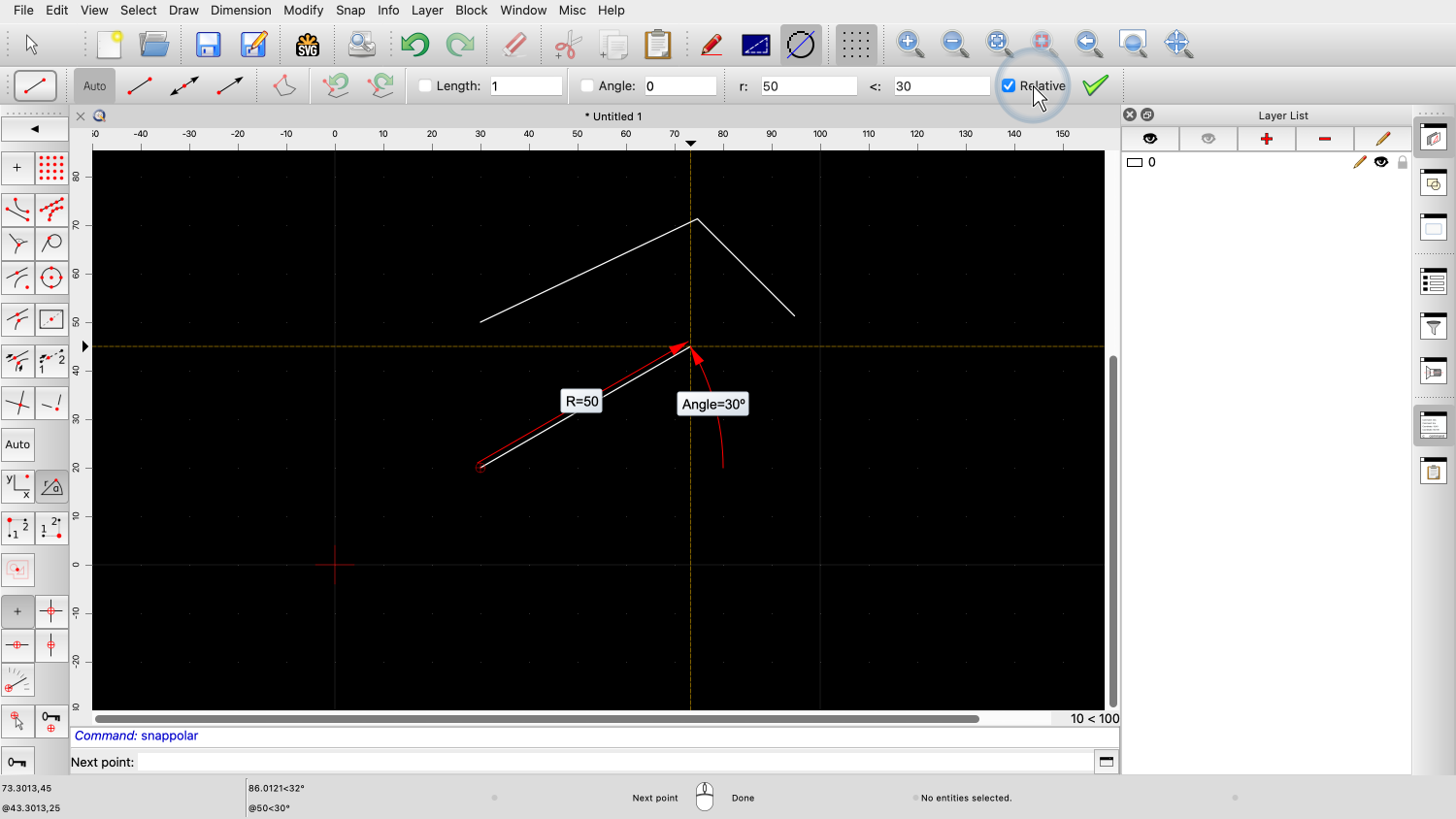
If we also activate relative coordinates, we can draw a line that is 50 units long at an angle of 30 degrees.

Angles are always measured counter-clockwise from the 3 o'clock position.
This is not the only way how we can enter coordinates or how lines with a given length and angle can be constructed.
We will cover alternative methods in a different tutorial.
You should now have a basic understanding of coordinates in the context of CAD.
Be sure to practice this with your own installation.
Thank you for watching this QCAD tutorial.