Video Transcript
In this QCAD tutorial, we will learn the basics about modification tools.
Example drawing: move_copy.dxf
We will look at the tool to move and copy entities and some of the tools for trimming.
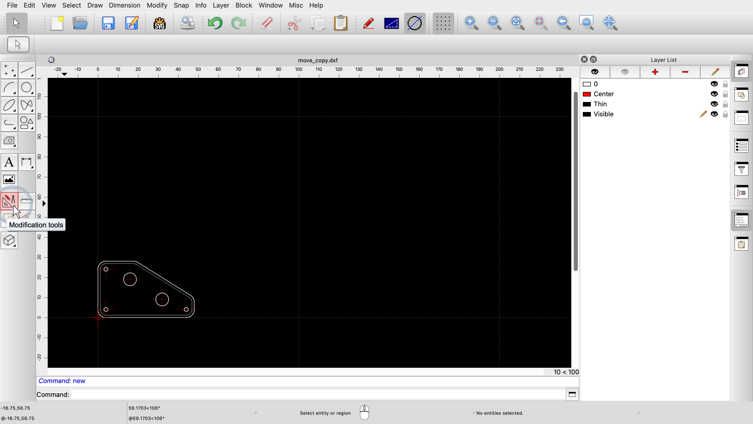
We can find the modification tools in the CAD toolbar at the left by clicking on the button with the protractor icon.
In our previous tutorial, we have learned the basics about selecting entities.
Many modification tools of QCAD operate on such a selection.
If no entities are selected, these tools are inactive and appear gray in the menus and toolbars.

For instance, let's consider the move and copy tool at the top of the CAD toolbar.

If we try to access the same tool from the menu, we find that it is also grayed out and inactive.
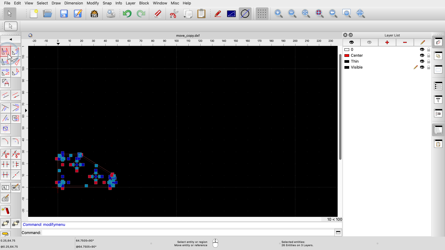
These inactive tools become active as soon as we select at least one entity.
By making a selection, we tell QCAD which entities to work with.
In this example, we tell QCAD which entities should be moved or copied.

As soon as we select some entities, the tool buttons and menus become active to indicate that they are now available.
For this brief introduction, we have a look at the move and copy tool of QCAD.
The tools to rotate, mirror or scale work in a similar way.

After starting this tool, QCAD asks us for a reference point.
This is the point we want to use to place the moved part in the drawing.

For this example, we choose a grid point as reference point.

We can now place the part at a new position in the drawing.
We place the copy to the right of the original part.
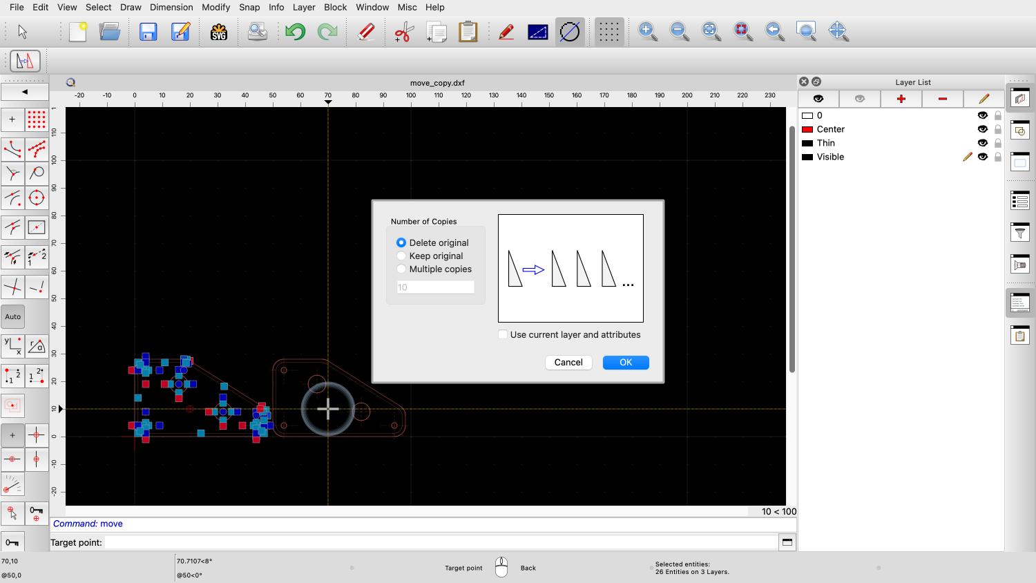
QCAD pops up a dialog that lets us choose if we want to delete the original part or keep it.

To delete the original part means that the original part is moved to the new location.

Keeping the original part creates a copy at the new location.
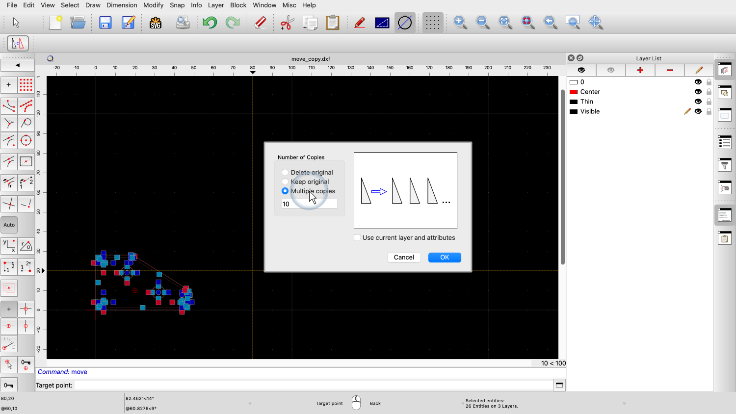
The third option allows us to create multiple copies.
With this option, we can create a whole row of copies in one step.
For this example, we create three copies.

This means, we will have four parts: the original one and our three copies.
Each copy is moved by the distance from the original to the first copy, creating a row of equally spaced parts.
We repeat this process for the whole row of parts to create three rows.

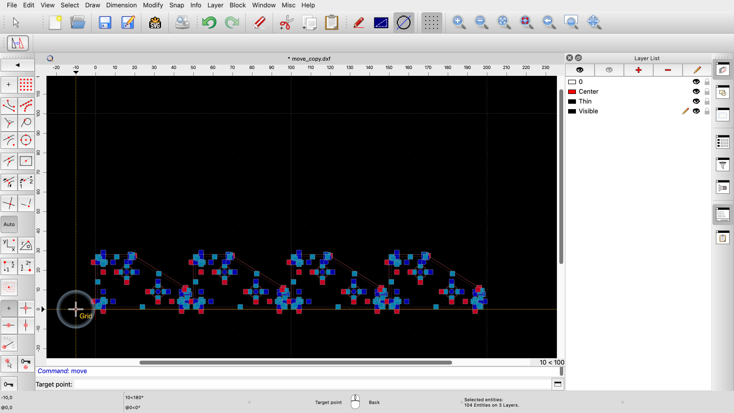
We can choose the reference point anywhere in the drawing, also away from our part to conveniently click grid points without auto snap snapping to undesired points.


We create two copies to create three rows. The original one plus two copies.
Example drawing: trim.dxf
There are also modification tools that do not require a selection.
These tools let us click one or several entities to modify.
In this example, we will recreate the drawing on the right.
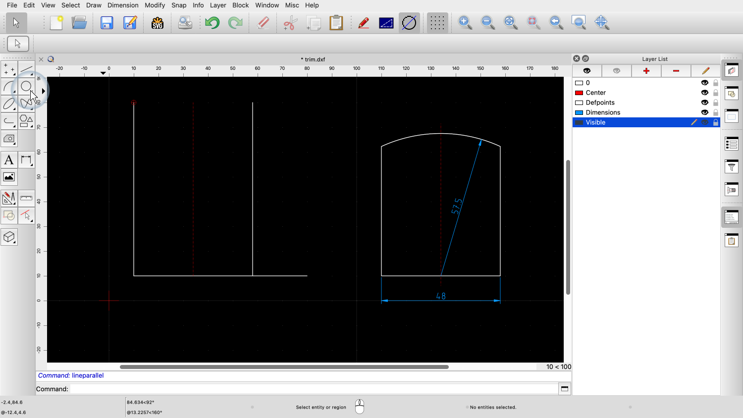
We start by drawing the two orthogonal lines that shape the bottom left corner.

Although, we could draw these to the right length, we choose to draw them deliberately too long using the grid.
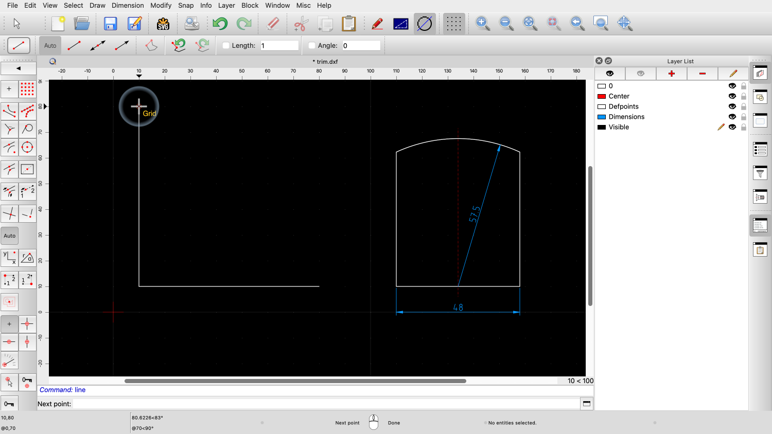
This is a technique that is often used in CAD to get the entities into the right place quickly without immediately worrying about their lengths.

Next, we draw the right edge using the parallel line tool.

We set the distance to 48 units.
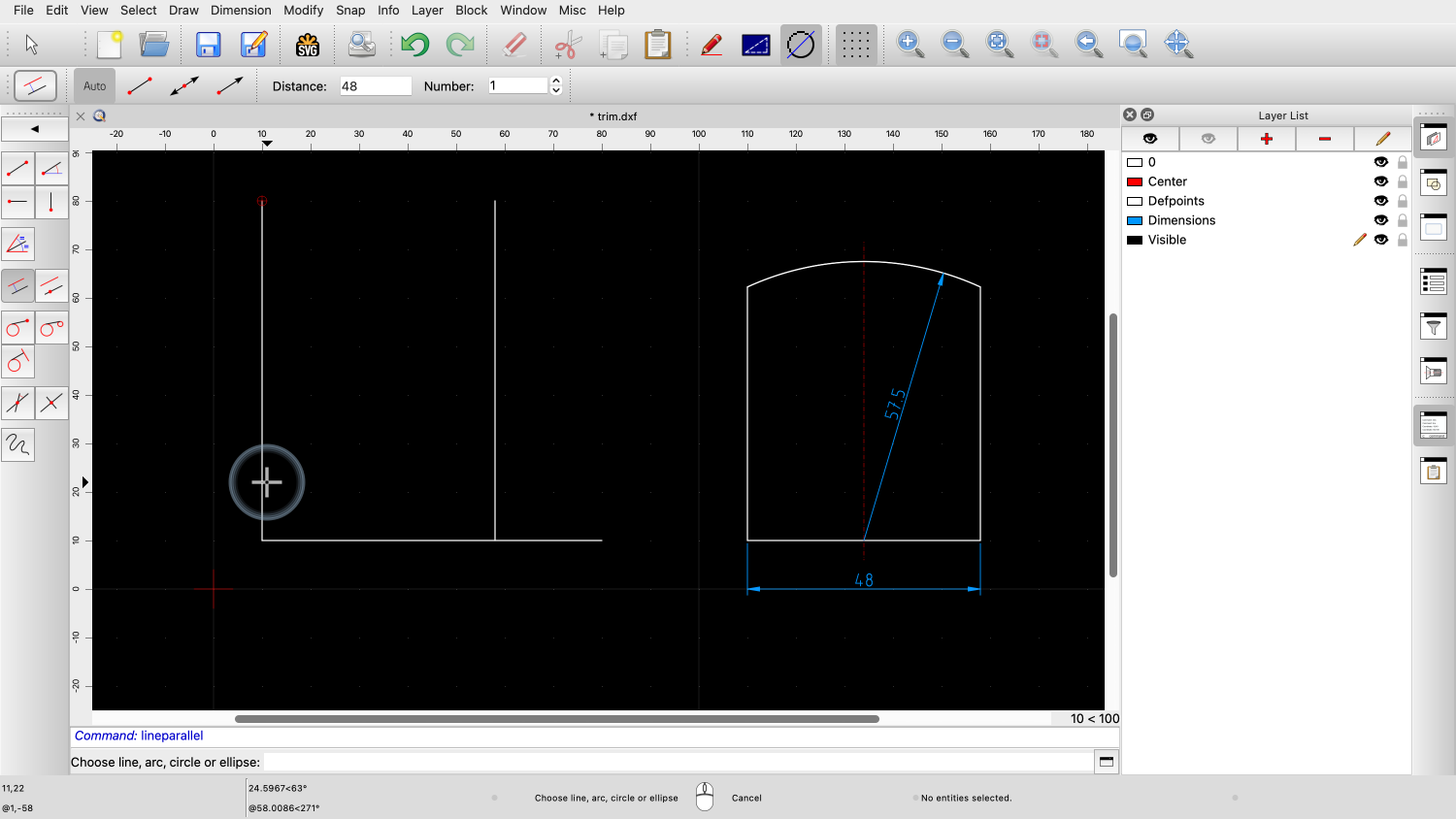
By clicking slightly on the right side of the existing line, we can tell QCAD that the parallel should be constructed on the right side of that line.
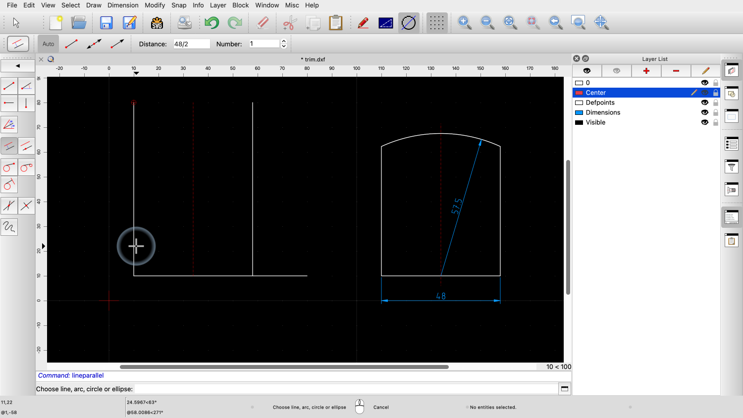
We create another parallel with half the distance on layer "Center" for the center line.


Now, we create a circle with the desired radius. We use the intersection at the bottom as center point.
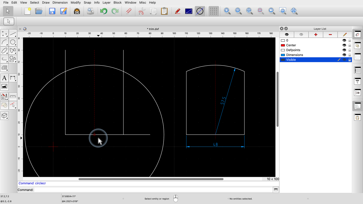
All the geometry we need is now in place.
We only have to trim the parts to their correct length.
For that, we can use the trim tools of QCAD.

The first trim tool we use, trims an entity to its intersection point with an other entity.
We can use this, to trim the center line to the circle line at the top.
We first click the limiting entity and then the entity we want to trim to the limiting entity.
Note that we click that part of the entity we want to keep, not the part to trim.

The limiting entity is the circle.
The entity to trim is the center line.

If we click the center line above the circle, the bottom part of the line is trimmed up to meet the circle.

Since we don't want that, we hit undo and click the line below the circle instead.
This tool is helpful if we want to trim one or multiple entities to a limiting entity without changing the limiting entity.

To trim two entities at once to form a corner, QCAD offers another trim tool.
This tool works in the same way as the first trim tool but trims both clicked entities to meet at their intersection point.


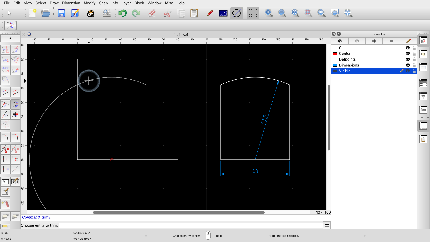

We can use this to trim the two corners at the top right and top left.
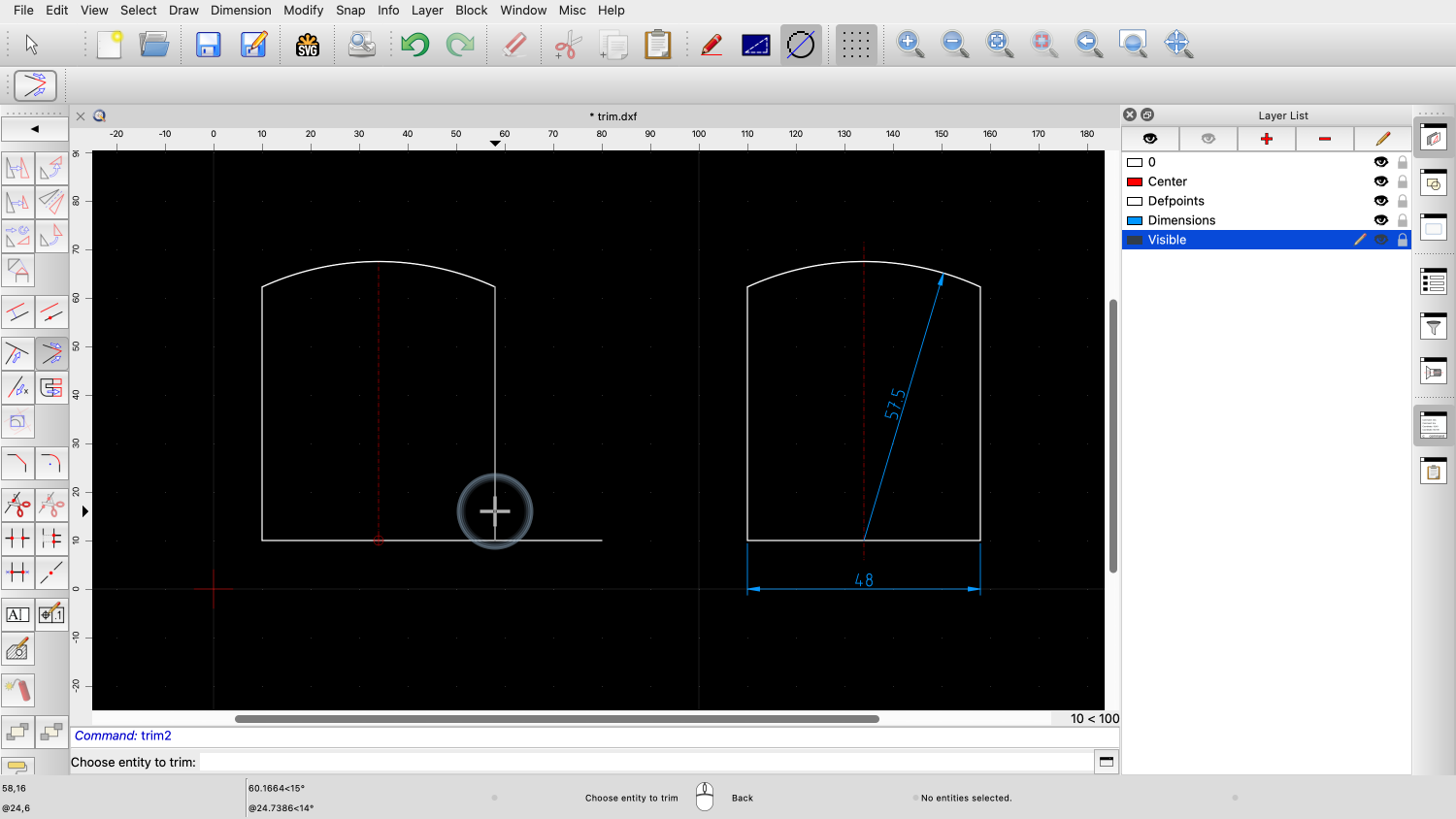

And we can also use this tool for the bottom right corner.

To extend the center line, we use another trim tool to lengthen the line by a given amount.

For the amount to lengthen, we enter 4.
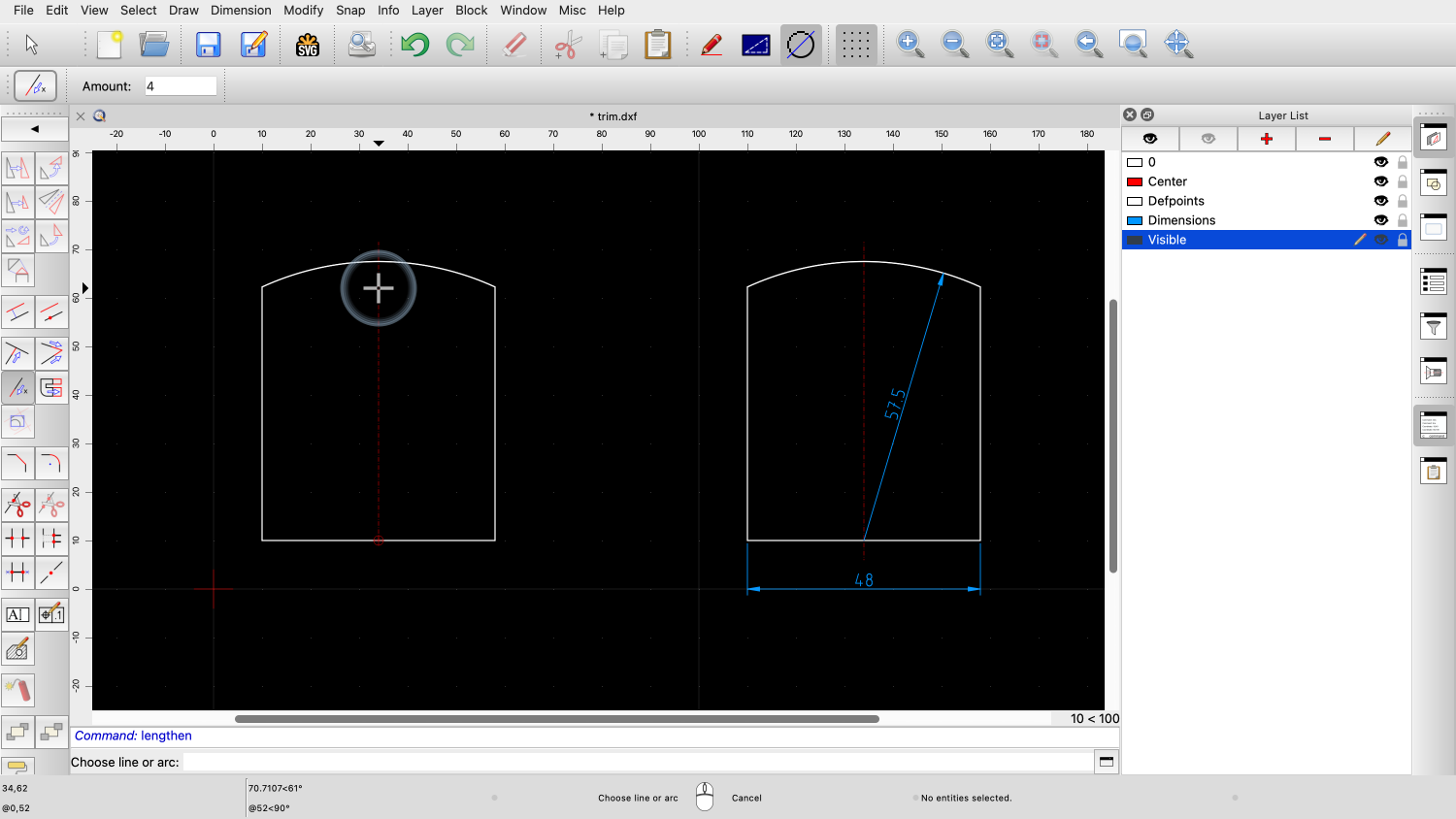
We simply click the line to lengthen the line by the amount we have entered.
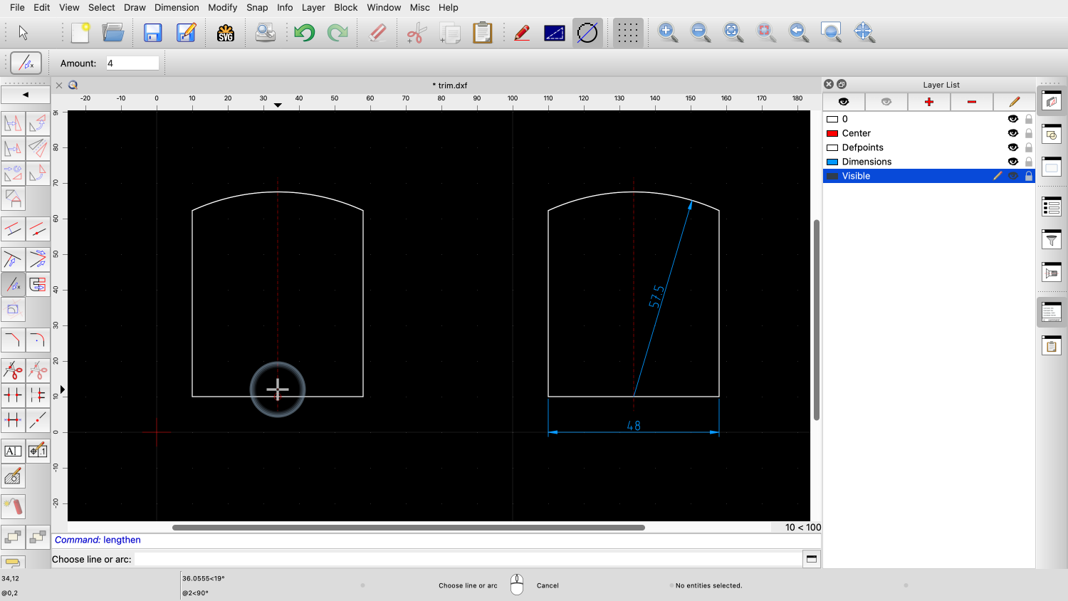

The line is extended at the end that is closer to the mouse cursor when we click.
You should now understand that some modification tools require a selection and others don't.
You should be able to create multiple copies of a selection and trim lines.
Be sure to practice this with your own installation.
Thank you for watching this QCAD tutorial.